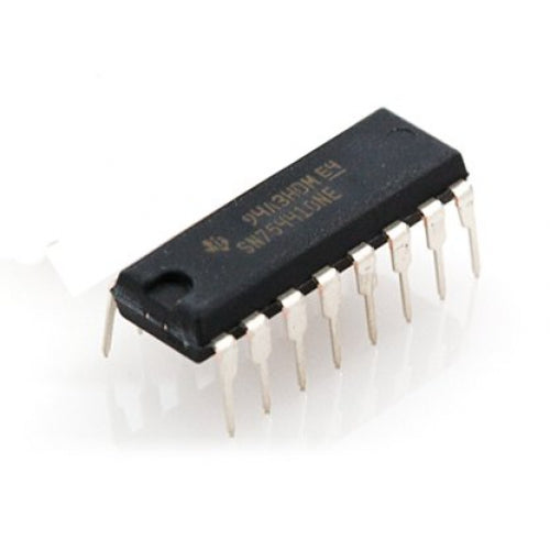
Motor Driver IC SN754410 - The SN754410NE from Texas Instruments is a quadruple half-H driver that can be used for bidirectional control of two DC motors or to control a single bipolar stepper motor. You can use this item as a replacement part, to stack on an existing motor controller, or to make your own motor or other high-current device controller.
This integrated motor driver has the same pinout as the L293 that is popular in robotics applications, and the SN754410NE has the additional benefits of built-in protection diodes across the power transistors and output current capability of 1 A per driver. For even higher current applications, it is possible to physically stack two devices on top of each other to get almost 2 A of drive current, though we recommend you use a higher power driver in those cases, such as our DRV8835 dual motor driver carrier or DRV8833 dual motor driver carrier.
 |
|
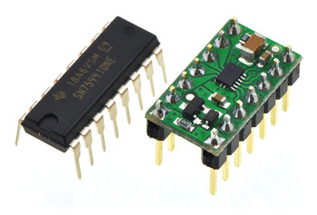
TI SN754410 (16-pin DIP) next to the DRV8835 dual motor driver carrier (14-pin DIP) for size reference. |
|---|
General specifications
| Motor driver: | SN754410 |
|---|---|
| Motor channels: | 2 |
| Minimum operating voltage: | 4.5 V |
| Maximum operating voltage: | 36 V |
| Peak output current per channel: | 1 A |
| Minimum logic voltage: | 4.5 V |
| Maximum logic voltage: | 5.5 V |
| Package: | 16-pin DIP |
Motor Driver IC SN754410 – Pins Configuration
- Pin 1 (Enable 1-2): The left side of the IC will operate if the enable pin is high; otherwise, it will not. A master control pin is another name for this pin.
- Pin-2 (Input-1): If the input pin is high, current will flow through pin 1 (output 1).
- Pin-3 (Output-1): The motor's terminals must be attached to this output-1 pin.
- Pin - 4 and Pin- 5 are ground pins.
- Pin 6 (Output-2) must be connected to one of the motor's terminals.
- Pin-7 (Input-2): If this pin is HIGH, current will flow through the output. 2
- Pin-8 (Vcc2): The voltage pin needed to power the motor is located here.
- The power source for the integrated circuit is pin-16 (Vss).
- Pin 15 (Input-4): When this pin is high, output-4 will be the path of current flow.
- Pin-14 (Output-4): This pin needs to be attached to a motor terminal.
- Pins 12 and 13 serve as ground pins.
- Pin-11 (Output-3): This pin needs to be attached to one of the motor's terminals.
- Pin-10 (Input-3): If this pin is high, current will flow through pin-3 when it is low.
- Pin-9 (Enable3-4): The right section of the IC will operate when this pin is high, and it will not operate when it is low. This pin is also known as the right part of the IC's master control pin.
L293D vs. SN754410 protection requirements
- The use of the L293D and SN754410 H-bridge for driving motors is the subject of some discussion. Both components are utilized on the AdafruitMotorshield, but due to the inductive kickback of a motor, there is some debate about whether the L293D can be directly replaced with the SN754410.
- The L293D calls out on the front page of the datasheet that the inbuilt diodes can safeguard the device from inductive kickback. Figure 3 shows the L293D operating a motor with no external protection. Only "ESD diodes" are mentioned in the SN754410, and Figure 3 depicts the SN754410 operating a motor with external protection.
- This seems reasonable at first glance. The SN745510 is rated higher at 1A with a higher forward voltage of 2.5V maximum, but the clamp ratings in the specification table for the L293D are 600mA with a forward voltage of 1.3V.
- If it is permitted, we would think that the SN754410 would work just as well in the same application as the L293D with no external protection if any inductive transients were within the listed ratings (same layout, supply levels, motor, etc.) The corresponding datasheets also include identical illustrations of the equivalent output structures.
Motor Driver IC SN754410
Motor Driver IC SN754410
Out of stock
Product Code
SKU:POL24
Couldn't load pickup availability


