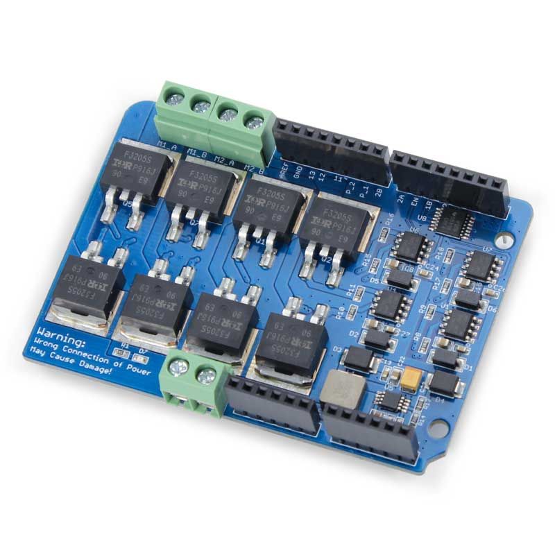
Looking for a reliable way to control powerful DC motors in your robotics or automation projects? The Dual Channel H-Bridge Motor Shield 22V 8A is a robust and efficient solution designed to give you full control over two motors independently. With its efficient H-bridge design, this shield ensures stable and responsive motor operation, making it ideal for high-power applications like smart vehicles, robotic arms, and industrial automation.
Whether you're a hobbyist or a professional, this motor shield is built to make your project more capable and responsive. It integrates easily with most Arduino boards and allows for flexible motor control, including direction and speed adjustments through simple digital and PWM signals. Built for performance and durability, it’s the perfect choice for those who want a powerful yet easy-to-use motor driver module in their toolkit.
FEATURES:
- Uses the IRF3205S MOSFET, which support max current up to 110A
- Uses Half bridge motor controller IR2104, to avoid H-bridge shortage.
- 2 Channels
- 2 oz cupper thickness, ensure larger current flow
Specifications:
- Type: Dual H-Bridge
- Motors: 2 DC
- Current: 8A
- Voltage: 22V
- MOSFET: IRF3205S
- Driver: IR2104
- Input: 7.4–11.1V LiPo
- Control: Logic/PWM
- PWM: 0–99%
- Board: Arduino-Compatible
Frequently Asked Questions:
1.) What is a dual H bridge?
Answer: The motor controller breakout board L298N Dual H Bridge Motor Driver is frequently used to control the speed and direction of motors. Additionally, it can be used to regulate the brightness of some lighting fixtures, including powerful LED arrays.
2.) Do H bridges need diodes?
Answer: Unfortunately, a single flyback diode is insufficient when using an H-bridge circuit. There must be four diodes to provide a path for the induced voltage due to the multiple current pathways.
3.) How does H-bridge control motor direction?
Answer: The two push-pull amplifiers on either side of the motor allow for the control of the current flow direction. Q1 turns off and Q2 turns on if S1 is depressed. If S2 is depressed at the same time, Q3 turns on and Q4 turns off.
4.) How many transistors does an H-bridge have?
Answer: The switch mode configuration of four NPN transistors (BC547) is used in the H-bridge. Transistors T1 and T2 as well as T3 and T4 each have an emitter and collector that are connected. The emitter of T2 and T4 is connected to the ground, and the collector of T1 and T3 is connected to VCC. Through resistors, T1 & T4 and T2 & T3's bases are connected.
TECHNICAL DETAILS
Dual Channel H-Bridge Motor Shield 22V 8A
Dual Channel H-Bridge Motor Shield 22V 8A
Out of stock
Product Code
SKU:ACS70028DH
Couldn't load pickup availability


