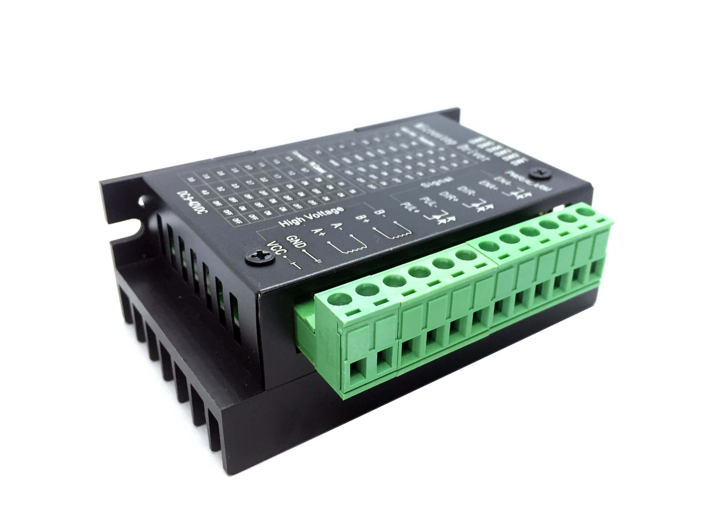
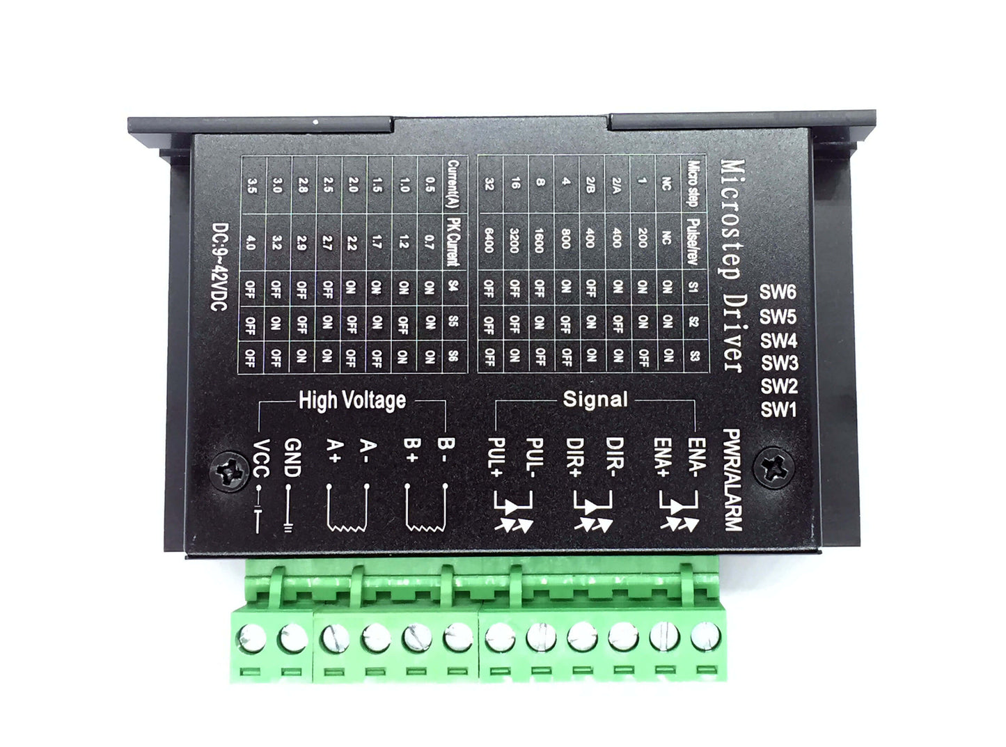
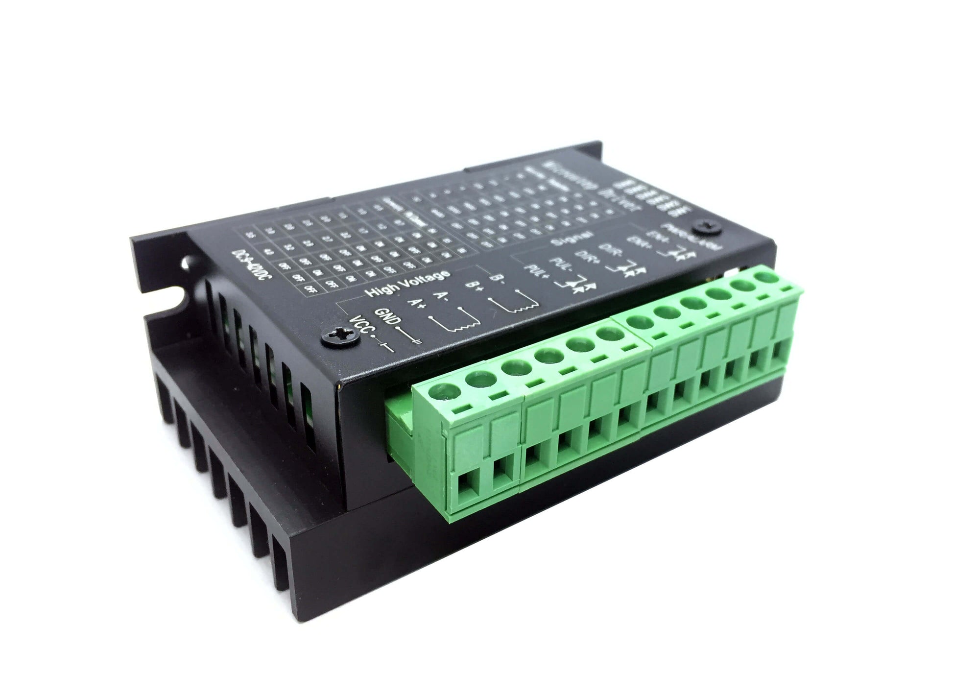
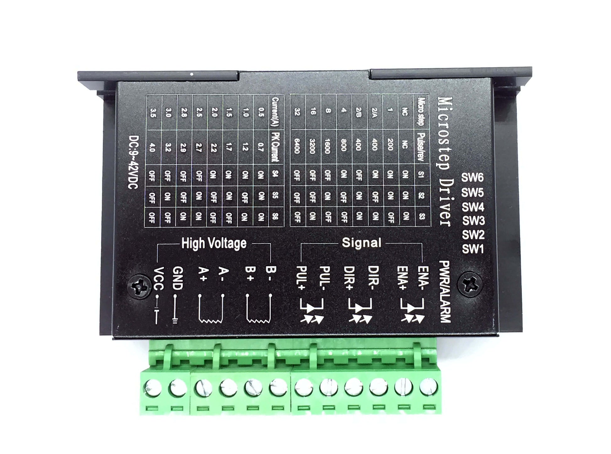
Stepper Motor Driver TB6600 - This driver can control a two-phase stepper motor. It is compatible with an Arduino board. It can have an input of 9 to 42VDC power supply and handle up to 4A peak current. The micro step and output current can be adjusted thru the 6 DIP switch.
And all signal terminals adopt high-speed optocoupler isolation, enhancing its anti-high-frequency interference ability.
It is also able to drive 57, 42-type two-phase, four-phase, hybrid stepper motor.
- Support 8 kinds of current control
- Support 7 kinds of micro steps adjustable
- The interface adopts high-speed optocoupler isolation
- Automatic semi-flow to reduce heat
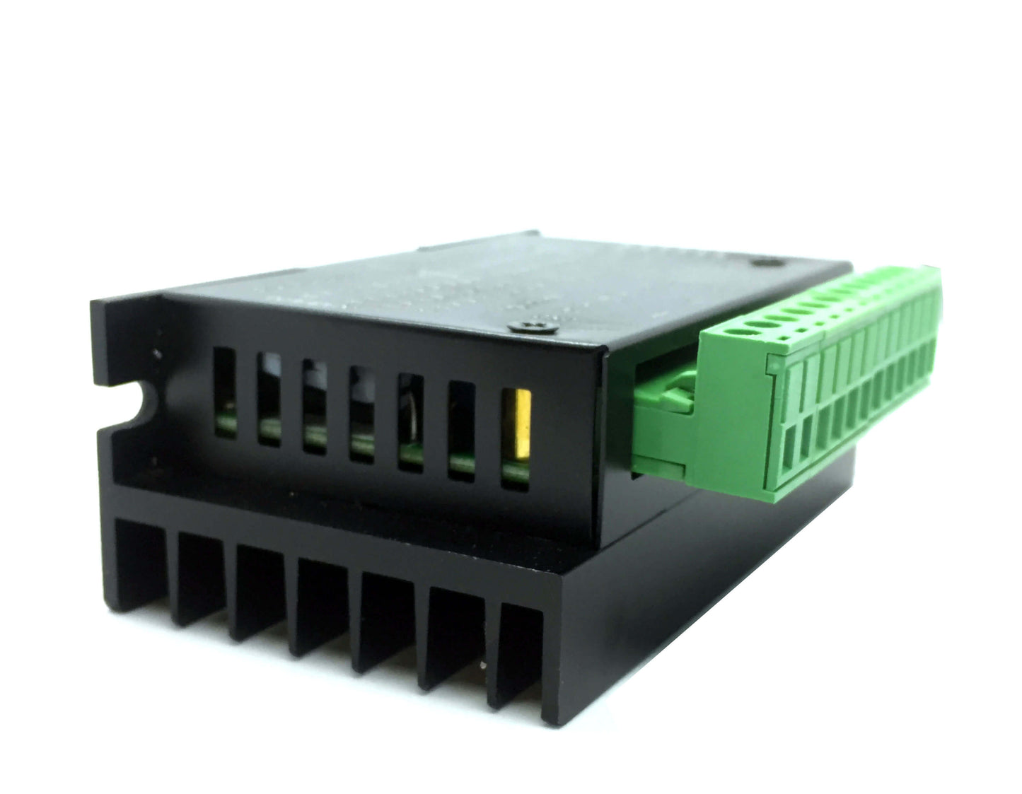
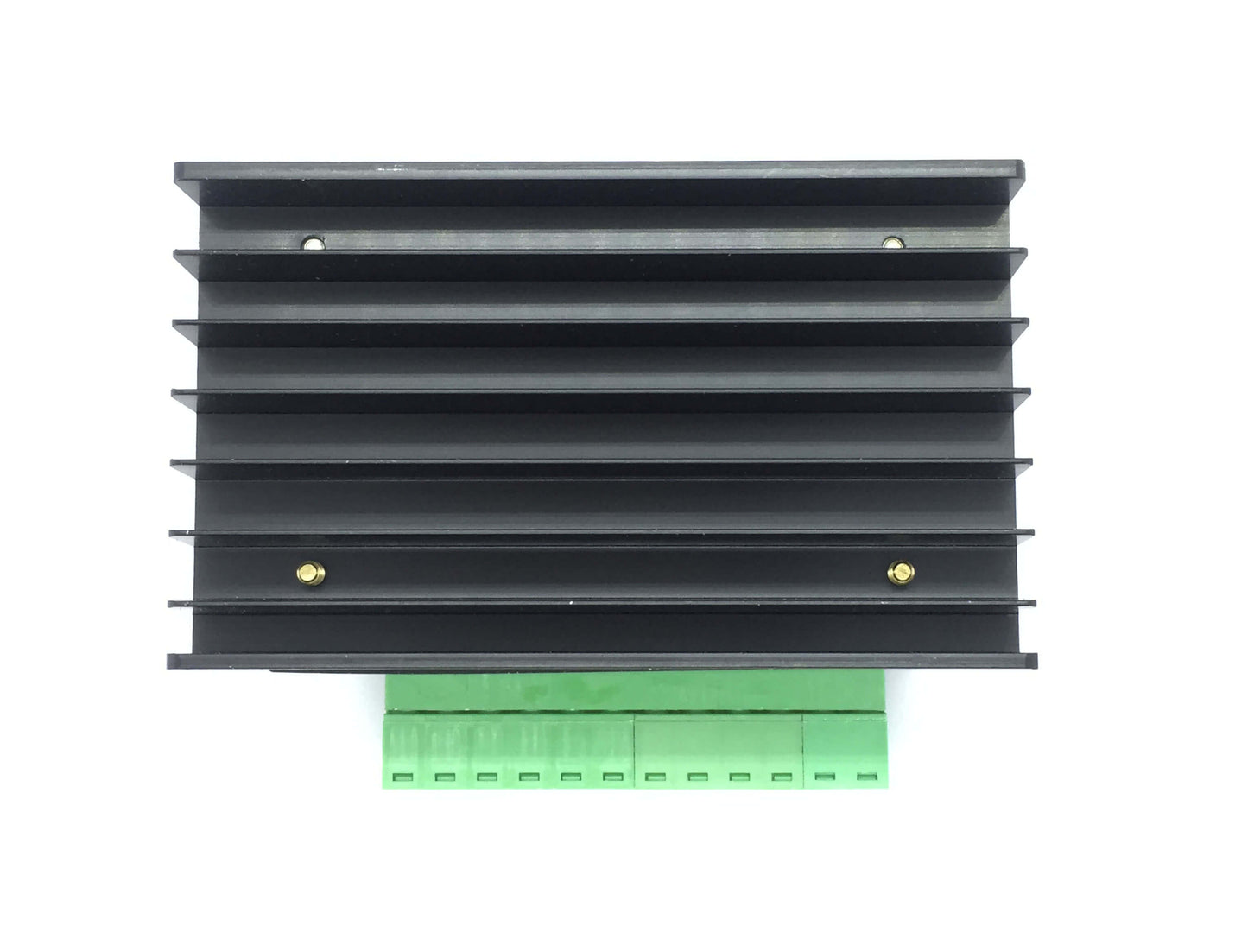
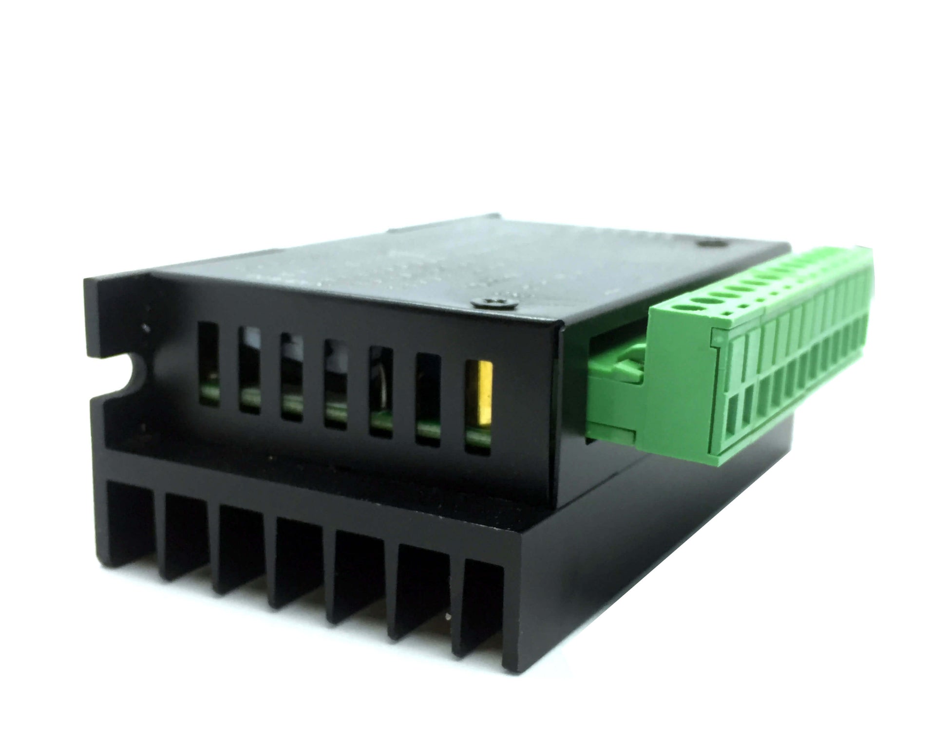
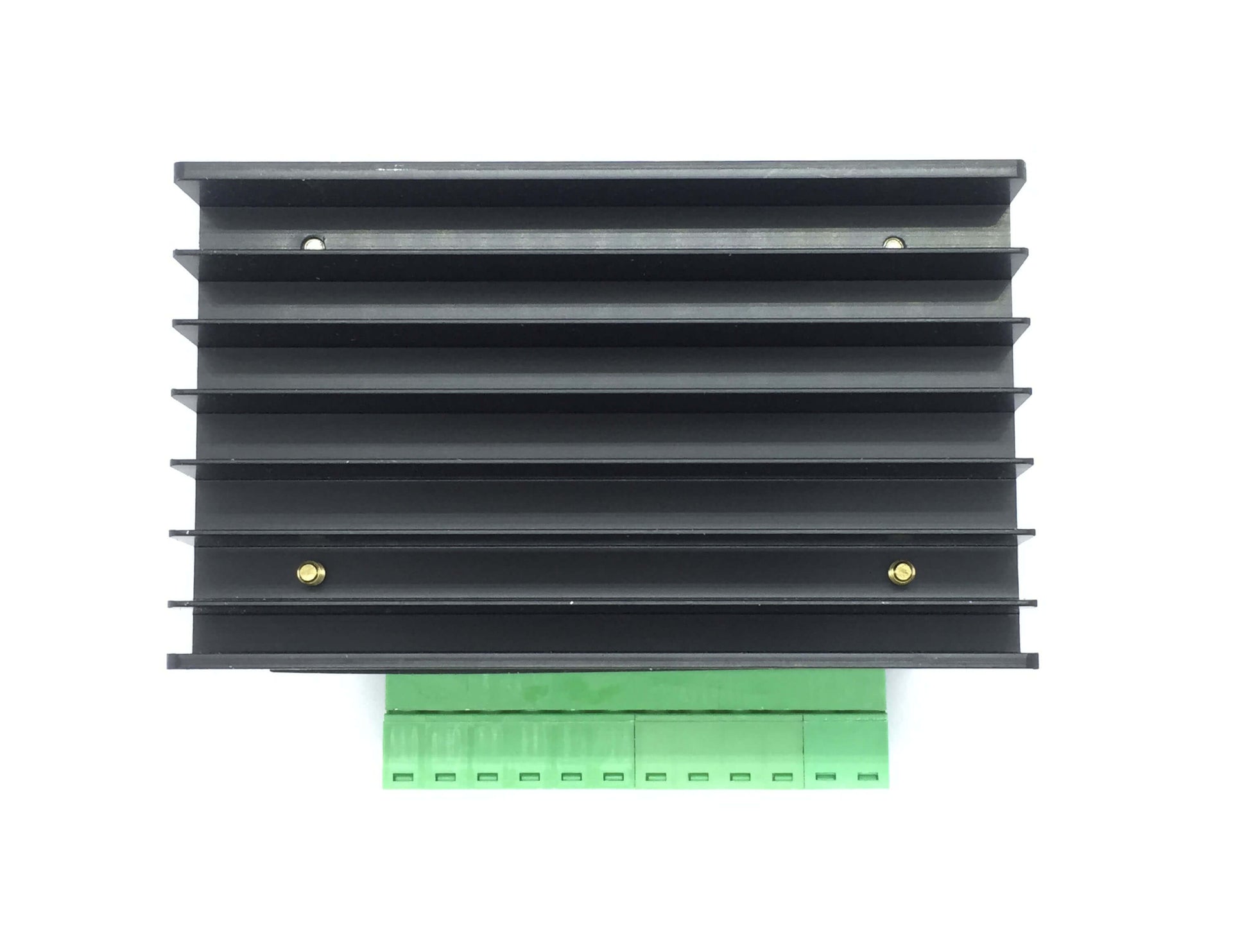
- Large area heat sink
- Anti-high-frequency interference ability
- Input anti-reverse protection
- Overheat, over current and short circuit protection
QUICK SPECS
- Input Current: 0~5A
- Output Current: 0.5-4.0A
- Control Signal: 3.3~24V
- Power (MAX): 160W
- Micro Step: 1, 2/A, 2/B, 4, 8, 16, 32
- Temperature: -10~45℃
- Humidity: No Condensation
- Dimension: 96*56*33 mm/ 3.78*2.2*1.3 inches
- Weight: 0.2 kg
- Drive IC: TB67S109AFTG
Frequently Asked Questions about Stepper Motor Driver TB6600
Q1: How Does a Stepper Motor Work?
Stepper motors are mostly used to regulate linear or rotational motion. When it comes to rotational motion, the shaft can revolve in distinct step increments by receiving digital pulses in the right order. A pulse can be created by microprocessors, timing logic, a toggle switch, or relay closure. A pulse is also known as a clock signal or stop signal.
Shaft revolutions are produced by translating a series of digital pulses. Each pulse required for a revolution is equal to one rotary increment or step, which is only a fraction of a full rotation. There are various connections between the input pulses and the rotation of the motor shaft. One such connection is between the rotation direction and the applied pulse sequence.
The device will rotate either clockwise or counterclockwise when the correct sequence of pulses is applied. The relationship between the frequency and speed of the input pulses and the rotation of the motor is another. Shaft rotation speed is increased by increasing input pulse frequency.
Q2: How to control a stepper motor?
Using a stepper motor driver alone is the fastest method of controlling a stepper motor (controller). And you only need a TB6600 Arduino.
The TB6600 Arduino is a professional stepper motor driver that is easy to use and capable of driving a two-phase stepping motor. It can emit a 5V digital pulse signal, therefore it works with Arduino and other microcontrollers that can. A variety of power inputs are supported by the TB6600 Arduino stepper motor driver's 9-42VDC power supply. And it can provide 4A of peak current, which is sufficient for the majority of stepper motors.
The stepper driver allows for both direction and speed control. With six DIP switches, you may adjust the output current and micro step. In total, there are 8 different types of current control (0.5A, 1A, 1.5A, 2A, 2.5A, 2.8A, 3.0A, 3.5A) and 7 different types of micro steps (1, 2 / A, 2 / B, 4, 8, 16, 32). Additionally, all signal terminals use high-speed optocoupler isolation, which improves the device's capacity to block high-frequency interference.
It can drive hybrid stepper motors of the 57, 42, and four-phase types as professional device.
Stepper Motor Driver TB6600
Stepper Motor Driver TB6600
Out of stock
Product Code
SKU:2501
Regular price
₱ 329.00
Regular price
Sale price
₱ 329.00
Unit price
per
Couldn't load pickup availability
