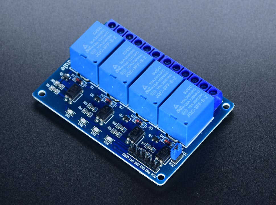
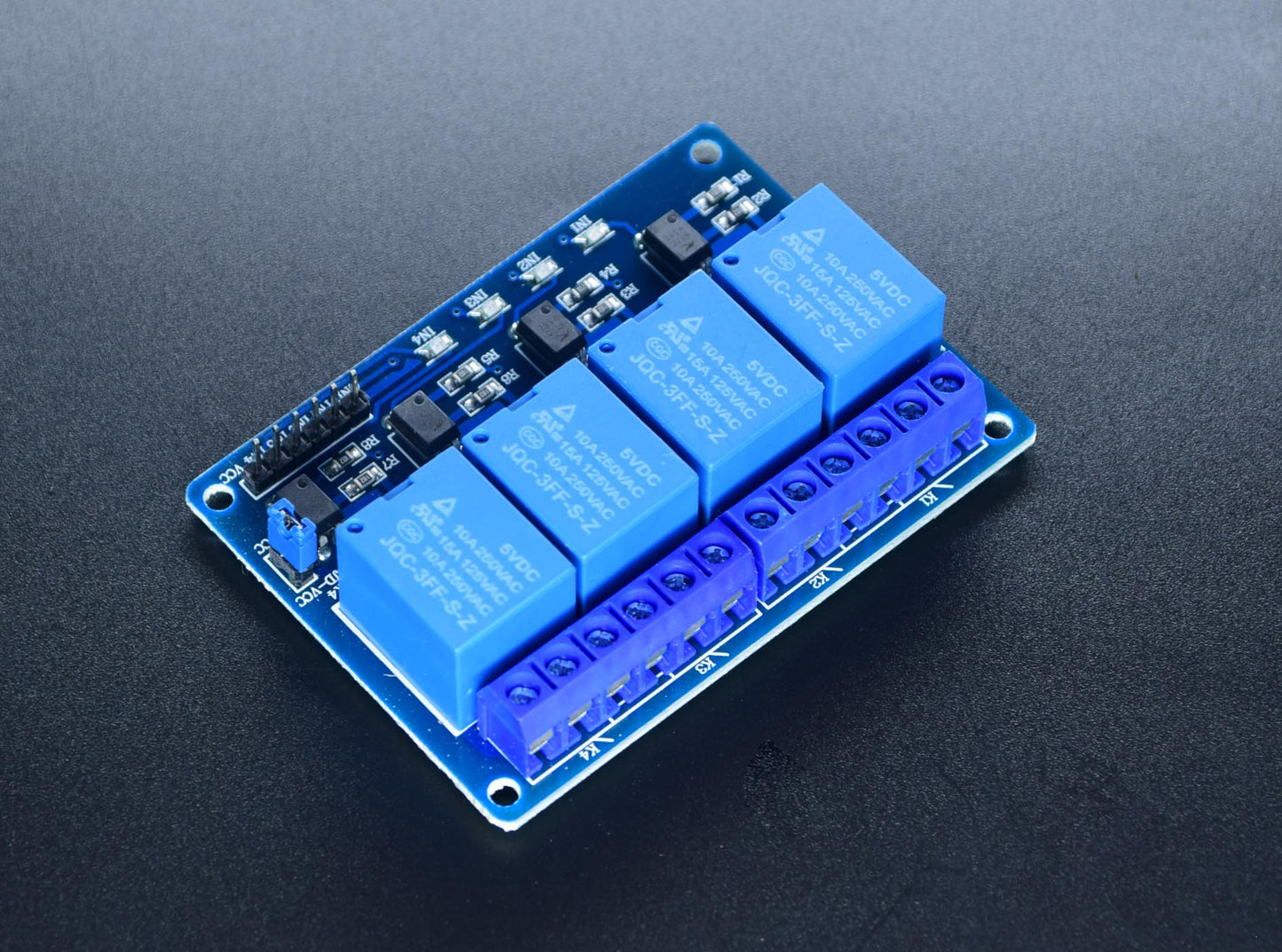
Relay Module 10A 4 Channel
Relay Module 10A 4 Channel - You may use a relay in controlling high-voltage components that your MCU could not, may it be AC or DC. A relay is a mechanical switch. What it does is to allow a current to flow or not, through the signal it receives. It has 3 terminals: Common, Normally Open, and Normally Closed. It also has 1 coil that does the cutting or allows the current to flow. As for the terminals, the Common Terminal and the Normally Close terminals have continuity without energizing the coil. When energized, the Common Terminal and the Normally Open Terminal will have the continuity, cutting the connection to the Normally Close Terminal. There is a boost in the development of Arduino projects. As of today, we come across an extensive range of Arduino integrations and project executions to develop performance-based and quality protocols.
The Arduino's 5V digital pin can control this relay. The max control capacity is 10A @ 250VAC or 10A @ 30VDC.
When energized, the Common Terminal and the Normally Open Terminal will have the continuity, cutting the connection to the Normally Close Terminal.
The Arduino's 5V digital pin can control this relay. The max control capacity is 10A @ 250VAC or 10A @ 30VDC.
We also have the 1 channel, 2 channel, 8 channel, and 16 channel versions.
QUICK SPECS:
Control Voltage: 5V DC
Max Control Capacity: 10A@250VAC or 10A@30VDC
4-Channel Relay Module – Product Description
In the flood of electronic inventions, Arduino, Raspberry Pi, and many other projects continue to revitalize advanced modules to perform better and strategically. This is the 5V 4-Channel Relay Module users can integrate across plenty of projects. Further, the optocoupler Relay Board Module is necessarily designed to control a range of microcontrollers, including Arduino, ARM, PIC, AVR, and many other integrations. In the flood of electronic inventions,Arduino, Raspberry Pi, and many other projects continue to revitalize advanced modules to perform better and strategically. This is the 5V 4-Channel Relay Module users can integrate across plenty of projects. Further, the optocoupler Relay Board Module is necessarily designed to control a range of microcontrollers, including Arduino, ARM, PIC, AVR, and many other integrations.
In addition to controlling Arduino projects, the 4-channel relay module is capable of managing various appliances and equipment with a larger current. It drives reliable current outputs to obtain desired results with the appropriate execution of microcontrollers and other related components. Primarily, the unit houses 3 terminals – Normally Open, Normally Closed and Common. Likewise, the module features a coil to further implement the cutting procedures for the current to flow independently. It drives reliable current outputs to obtain desired results with the appropriate execution of microcontrollers and other related components. Primarily, the unit houses 3 terminals – Normally Open, Normally Closed and Common. Likewise, the module features a coil to further implement the cutting procedures for the current to flow independently.
When it comes to terminals, the Normally Closed and Common terminals possess the potential to flow continuously without hindering the coil functions. The 5V 4-Channel Module unites an interface board with each channel requiring a 15-20mA driver current.It is further equipped with high-current relays that have the stamina to perform under AC250V 10A or DC30V 10A. It is further equipped with high-current relays that have the stamina to perform under AC250V 10A or DC30V 10A. Its standard interface helps control the microcontroller directly.
Relay Module – A Digital Switch to Control Higher Voltages & Currents
It isn’t a deeper inspection and analysis to describe a relay module in a standard context. It is simply a digital switch that is dedicatedly designed to control and manage higher voltages and currents than normal Arduino boards.The logic voltage permits the switch to allow current to flow or cut off, depending upon the situation. Overall, a Relay unit normally incorporates one Normally Closed terminal, one Normally Open terminal, and a Common terminal. Also, there is an integrated coil as well.
Apart from managing Arduino projects, the 4-channel relay module also possesses proficiency in managing multiple appliances and equipment. the best part is that it controls a larger current and undergoes reliable current outputs to capture desired results with the precise execution of microcontrollers. The standard interface of the unit helps control the microcontroller to a great extent.
Major Highlights & Features
Do you look for switching on your Raspberry Pi? The 5V 10A 4-Channel Relay Module is a perfect development for you. The neat relay unit houses 4 x 5V relays that are rated at 10A/250V each. The prime intention behind the idea is to switch up to 4 high current/high voltage loads with the help of microcontrollers.
With a perfect tag of 3 terminals, the Relay Module features 4 channels to derive the central force when it comes to authenticating the whole concept. It involves a pull-down circuit to avoid the happening of malfunctions and bring a healthy atmosphere altogether. Also, the module reflects a control pin of high impedance and increasing relay coil. Ultimately, the 5V 4-channel relay module is all set to accommodate your needs according to the potential your project requires for the given task. The three terminals help centralize the coil to derive desired performance.
People Also ask:
Q1: How can you tell if a relay is functioning properly?
A coil, a pole terminal, and a series of contacts are typically present in a relay. Normal open (N/O) contacts are the set of connections that are open when the relay is not electrified, and normally closed (N/C) contacts are the set of connections that are closed when the relay is not energized. The relay can be tested using a multimeter by doing the subsequent procedures.
- Maintain the conductivity check mode on the multimeter.
- Verify that the N/C connections and pole are connected continuously.
- Verify that there are no gaps between the N/O connections and the pole.
- The relay is now powered using the recommended voltage. Use a 9V battery, for instance, to power a 9V relay. Relay engagement will be audible clicking.
- Next, verify for continuity between the pole and N/O contacts.
- Additionally, look for any gaps between the pole and N/C contacts.
- As a last check, use a multimeter to measure the relay coil's resistance and see if it matches the value specified by the manufacturer.
- If the results of all the tests indicate that the relay is functioning properly.
Q2: How does a 4-channel 5 V relay operate?
The ability to operate higher voltage (120-240V) home equipment including fans, lighting, heaters, and other appliances is one of the most valuable things you can accomplish with an Arduino. However, you may use a 5V relay to switch the 120-240V current and use the Technology to control the relay as the Arduino only functions at 5V and cannot control these higher voltage devices directly.
When a specific condition arises, such as when the reaction of a photoresistor falls below 400 Ohms or when the heat of a thermistor rises above 30° C, the Arduino can be configured to activate the 4 channel relay module. Most of the sensors can be used to activate or deactivate the relay. Even a sensor is not required as the source of the trigger. It can start when a button is pressed, at predetermined intervals, or even when you receive an email.
Three high voltage terminals (NC, C, and NO) on the four-channel relay module connect to the object you want to operate. Three low voltage pins (Ground, Vcc, and Signal) on the opposite side are connected to the Arduino.
Normally closed terminal: 120-240V terminal
No, the 120-240V terminal is normally open.
C: Common endpoint
(Joins with the Arduino's ground pin, Connects to the Arduino's 5V pin using 5V Vcc, It carries the Arduino trigger signal, which fires the relay). A 120–240V switch coupled to an electromagnet is located inside the relay. The electromagnet charges up and moves the switch contacts open or closed when the relay detects a HIGH signal at the signal pin.
Major Highlights & Features
Do you look for switching on your Raspberry Pi? The 5V 10A 4-Channel Relay Module is a perfect development for you. The neat relay unit houses 4 x 5V relays that are rated at 10A/250V each. The prime intention behind the idea is to switch up to 4 high current/high voltage loads with the help of microcontrollers.
The 4-Channel Relay Module brings tons of productive features users can cultivate to contain the desired outcomes. Now is the time to analyze some of the top reflections of the Relay Module:
- The 4-channel board connects 3 terminals (Common, Normally Open, and Normally Closed) as well as a coil.
- The unit integrates 4 channels to create a central force for the entire project.
- Further, the 4-channel Relay Module stays fruitful while controlling various appliances and other developments.
- It can control the 220V AV load.
- There is a pull-down circuit integrated to prevent the occurrence of malfunction.
- The input signal, signal, common Terminal, and start conducting;
- There is a high impedance control pin.
- Likewise, the 4-channel Relay Module abides by international safety standards, load area isolated trenches, and controls.
- Relay Operating Voltage: 3.3V to 5V
- Triode drive, increasing relay coil
- Power supply and relay instructions, lit, a disconnect is off;
Relay Module 10A 4 Channel
Relay Module 10A 4 Channel
Low stock: 9 left
Product Code
SKU:2384
Couldn't load pickup availability


