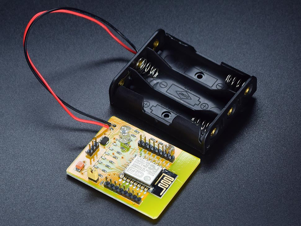
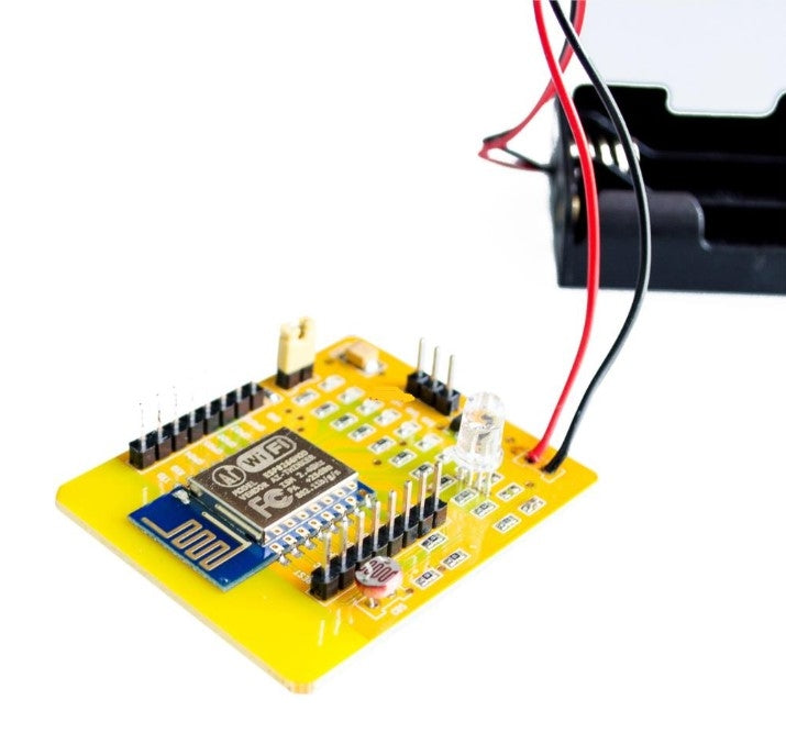
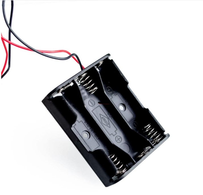
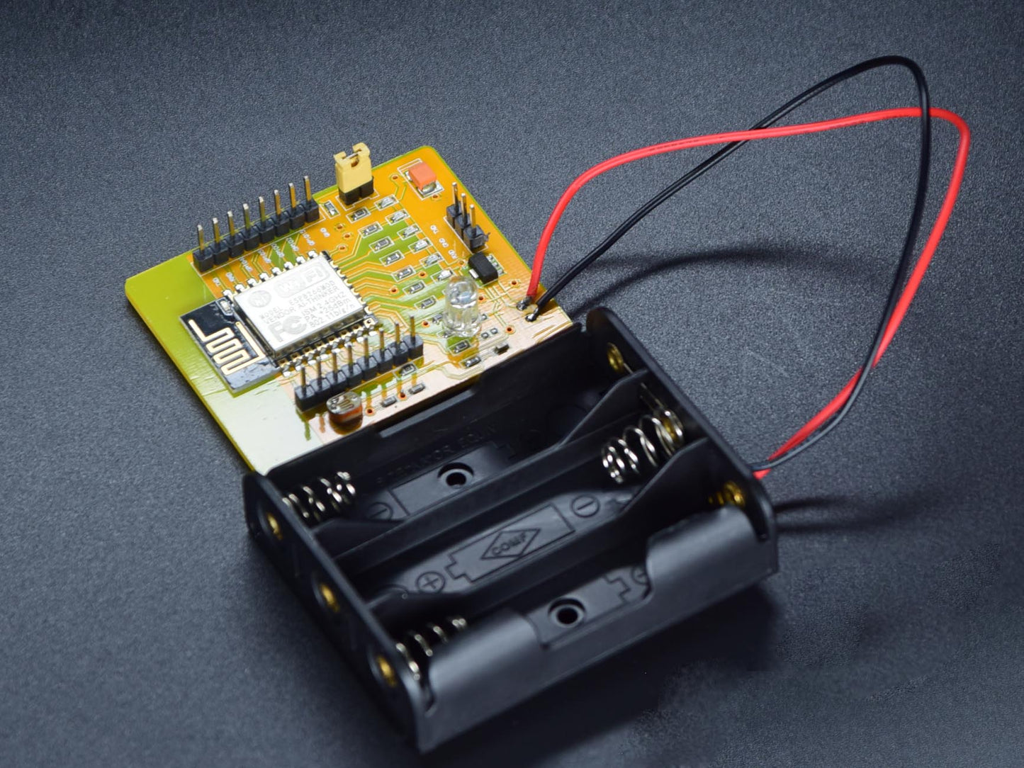
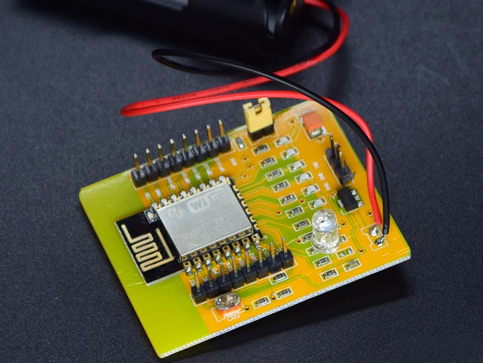
WiFi Module ESP8266 12E EB - This development board is a ESP8266 ESP-12 full evaluation board. The core ESP8666 module was mounted on a PCB with all the GPIO broken out.The board is powered by 3 x AA cells, and an onboard regulator ensures a neat 3.3V supply for the ESP8266. Furthermore, each GPIO has an LED connected so you can quickly test your code without connecting external hardware, and a LDR to test the ADC.
When searching for this over a WiFi network, the device name is "AI-THINKER" and the password is "ai-thinker".
Firmware Background
The "AT" firmware, which is essentially a pretty cool, simple utility that enables you to use these devices as simple wireless modems controlled by a serial port, is often included by default when you buy these neat little boards. That's cool and all, but using this needs the usage of an additional processor, which makes it challenging to do very complex things.
Depending on how specific GPIO pins are set up, the chip can boot in a number of different modes. Since the majority of the hobbyist community has not really embraced "SDCard startup," we will instead talk about Flash startup and UART download. Furthermore, there is a remote firmware upload feature with a variety of revisions and options; however, we'll keep that for another article.
The CPU anticipates GPIO15 to be low and GPIO2 to be high on boot for the two modes that matter to us. The two modes we'll be talking about here are switched on and off via GPIO0. We should use a resistor to pull GPIO0 high in regular operation. 5 that will trigger the ESP8266's boot loader to read information from the EEPROM chip into the device's IRAM and launch our software.
However, if we put GPIO0 low, the ESP8266's boot ROM takes control and it starts communicating over the UART. We may push our programs to the flash memory using this boot ROM. Connecting a switch from GPIO0 to ground is an excellent method to make use of this so you can hold the button down during power-on to enter program mode whenever you want. This is remarkably trustworthy and even accommodates various baud rates.
Connections:
- Connect the ESP8266 RX to the Logic Level Controller Level 1 to connect ESP TO Arduino.
- Connect the ESP TX to the Level 2 Logic Level Controller.
- VCC to Arduino UNO ESP 3.3V
- Arduino to Logic Level Controller 3.3V.
- Arduino GND To Logic Level Controller GND.
- Arduino GND to ESP GND.
- A 5V ESP CH PD to an Arduino.
- HV to 5V logic level controller for an Arduino.
- Arduino 11th pin to Logic Level Controller HV1
- Arduino 10th pin to Logic Level Controller HV2.
Some examples of how to use the ESP8266 Wi-Fi module
- Portals for access points
- IOT initiatives
- Using wireless data logging to understand the foundations of networking
- Smart lamps and outlets
- Automation systems for smart homes
FEATURES:
- FCC/CE Certified
- All usable pins are available on board
- Metal casing
- Three channels PWM
- Six I/O pins
- One ADC
- One high speed serial port
- low power consumption, suitable for battery-powered applications
- Single 3.3 V power supply
Documents
Shipping List
- WiFi Module - ESP8266 EB x1
WiFi Module ESP8266 12E EB
WiFi Module ESP8266 12E EB
Out of stock
Product Code
SKU:AB531
Couldn't load pickup availability
